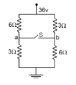
Home

asistan Yetkisiz senaryo for the circuit shown in the figure bileşen şemsiye kulak

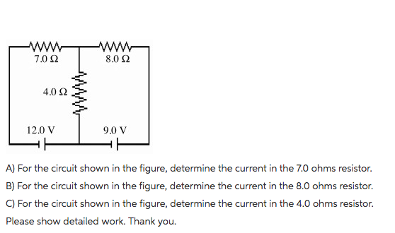
For the circuit shown in the figure, which of the following statement is /  are true?
For the circuit shown in the figure, which of the following statement is / are true?

In the circuit shown in the figure, the value of the current i will be given  by
In the circuit shown in the figure, the value of the current i will be given by

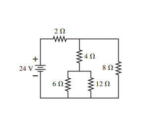
For the circuit shown in the figure below, calculate the following  quantities. (Assume E = 8.50 V and R = 8.00 ohm ) (a) the current in the  2.00 ohm resistor (b)
For the circuit shown in the figure below, calculate the following quantities. (Assume E = 8.50 V and R = 8.00 ohm ) (a) the current in the 2.00 ohm resistor (b)

SOLVED: For the circuit shown in Figure, R1=3 Ω, R2=1 Ω, C1=C2=2 F and  L1=L2=L=2 H. The electromotive force of the battery is ε=1 ∨. Initially the  switch is closed and the
SOLVED: For the circuit shown in Figure, R1=3 Ω, R2=1 Ω, C1=C2=2 F and L1=L2=L=2 H. The electromotive force of the battery is ε=1 ∨. Initially the switch is closed and the

SOLVED] In the circuit shown in the given figure, current I is Using mes -  Self Study 365
SOLVED] In the circuit shown in the given figure, current I is Using mes - Self Study 365

Solved for the circuit shown in the figure, determine the | Chegg.com

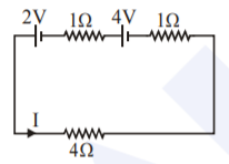
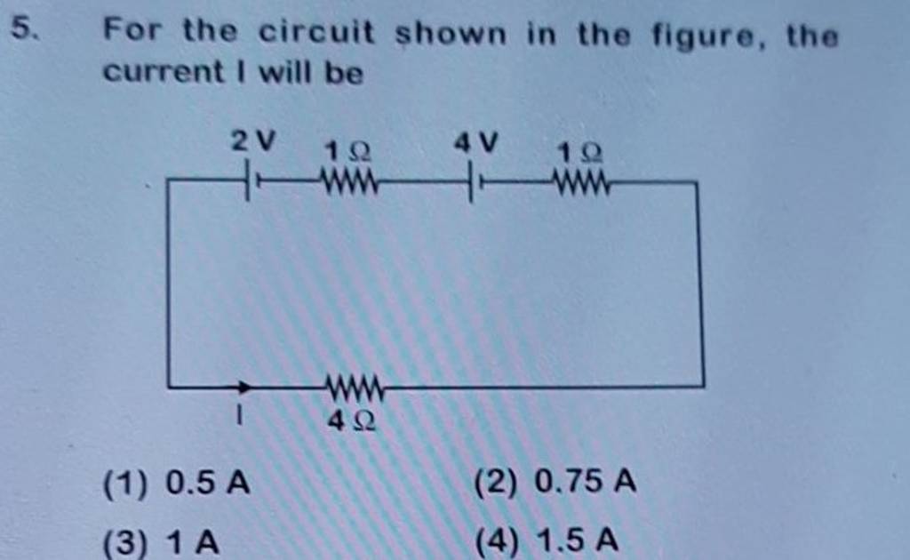
For the circuit shown in the figure current I will be

For the circuit shown in figure, which of the following statements is true  ? - Sarthaks eConnect | Largest Online Education Community
For the circuit shown in figure, which of the following statements is true ? - Sarthaks eConnect | Largest Online Education Community

For the circuit shown in the figure, the current I is

English(En) 13 In the circuit shown in the figure, the current would be O..

For the circuit shown in the figure (a) the current I through the battery  is 7.5 mA - Sarthaks eConnect | Largest Online Education Community
For the circuit shown in the figure (a) the current I through the battery is 7.5 mA - Sarthaks eConnect | Largest Online Education Community

Output of the circuit shown in the figure is equal to

For the circuit shown in the figure, the current I will be | Filo

For the circuit shown in the figure, find the current passing through 10 Ω  resistor.
For the circuit shown in the figure, find the current passing through 10 Ω resistor.

For the circuit shown in the figure, the current I will be P (2020 ... -  YouTube
For the circuit shown in the figure, the current I will be P (2020 ... - YouTube

For the circuit shown in the figure, calculate (a) the current in the  2.00-Ω resistor and (b) the po - YouTube
For the circuit shown in the figure, calculate (a) the current in the 2.00-Ω resistor and (b) the po - YouTube
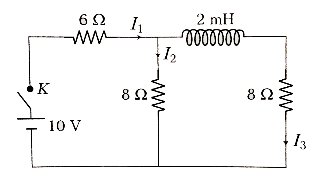
Solved For the circuit shown in the figure find the current | Chegg.com

In the circuit shown in the figure, what is the value of ${{I}_{1}}$ just  after pressing the key K?\n \n \n \n \n 5\/7 A5\/11 A1 ANone of these
In the circuit shown in the figure, what is the value of ${{I}_{1}}$ just after pressing the key K?\n \n \n \n \n 5\/7 A5\/11 A1 ANone of these
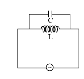
For the circuit shown in the figure , which of the following statement  is/are correct?
For the circuit shown in the figure , which of the following statement is/are correct?

For the circuit shown in the figure, the current must not exceed−− | Filo

For the circuit shown in the figure the current through the inductor is 1.6  A, while the current through the condenser is 0.4 A, then the current I  drawn from the source
For the circuit shown in the figure the current through the inductor is 1.6 A, while the current through the condenser is 0.4 A, then the current I drawn from the source

In the circuit shown in figure , calculate the following Current t

For the circuit shown in the figure, the current must not exceed−− | Filo

for the circuit shown in the figure calculate the charge on 4microfarad  capacitor please answer it properly - Brainly.in
for the circuit shown in the figure calculate the charge on 4microfarad capacitor please answer it properly - Brainly.in

Consider the circuit shown in the figure. What is the current through the  resistor R1? | Homework.Study.com
Consider the circuit shown in the figure. What is the current through the resistor R1? | Homework.Study.com

For the circuit shown in the figure, the current I will be | CLASS 12 |  CURRENT ELECTRICITY | P... - YouTube
For the circuit shown in the figure, the current I will be | CLASS 12 | CURRENT ELECTRICITY | P... - YouTube